A: When it is acting as a simple delay line
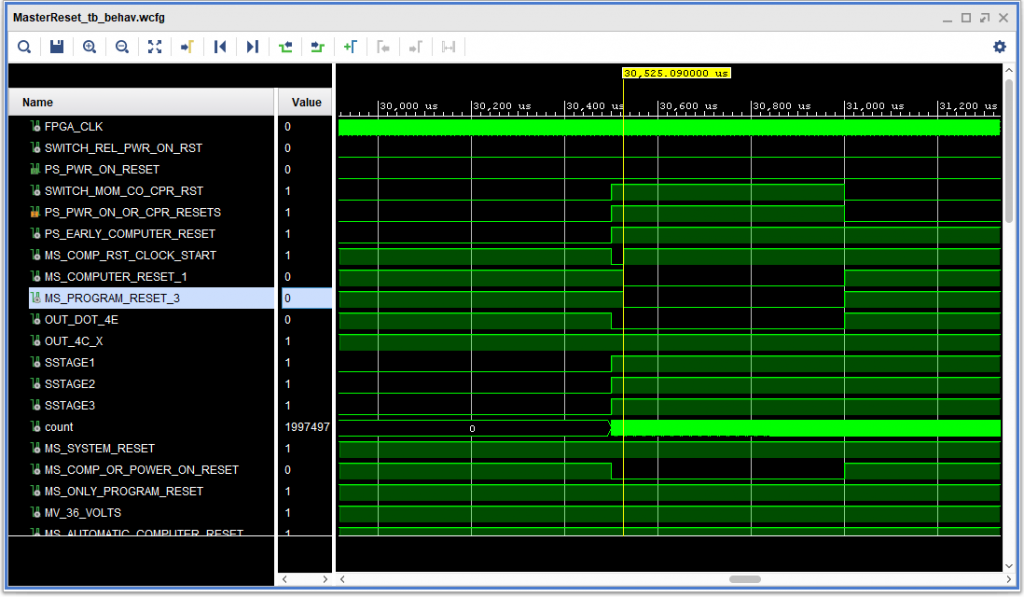
While working on ALD page 12.65.01.1, which generates power on and computer reset signals, I noticed something that didn’t look quite right. The computer reset signal (active negative) when negative when the button push was simulated, then went back inactive, then went active again 25 microseconds later – when it was actually supposed to go active (the result of the timeout of a 25 microsecond single shot gate).
Puzzling – the logic all looked fine. What was going on? At first I thought, “so what – it is going to reset anyway — so no big deal”. But then I looked at the IBM 1410 system fundamentals document, S223-2648, page 26, which makes it pretty clear that the computer reset signal should only be active after the computer reset clock start single shot times out, indicating that the logic gate should stop at either state A or state R. But why?
Then it hit me: CORE STORAGE. If one resets the machine at the wrong time – say, in between reading a character from core (which is a destructive operation) and writing it back, bad things would happen. — the character would be erased. But, how did the actual machine avoid this problem? Sure, I have a relatively long (90 ns, with a 100MHz FPGA clock) single shot setup time to detect the rising edge of an asynchronous trigger on the single shot, but regardless, that setup time would not be 0.
Then I saw it: A 0.047 microfarad capacitor in the ALD page 12.65.0.1 between that computer reset signal and logic ground. Ah HA! A delay!
Fortunately, I had already learned how to implement a delay on an FPGA: with a “bucket brigade” delay line – whose length determines the delay. Sticking a 4 cell (120 ns) delay at that point in the circuit fixed things up just fine.
The results are shown in the simulated ‘scope trace, below. (The count signal and SSTAGE# signals below are for a different 20 millisecond single shot.)

