
The last issue that I had running the 1401 diagnostic (aside from Console I/O input working in neither 1410 nor 1401 mode) was “ERR ?3S” in diagnostic M011A, which corresponds to diagnostic location 07032 (the routine actually starts at location 06980). This is test RN111, the very last test in the diagnostic.
The diagnostic comment block says it all:
RN111
TURN ON OVFVLW IND WITH ADD INSTR
EXECUTE BR INSTR WITH UNITS PSN OF
A ADDR CONTAINING Z
TEST FOR OVLW IND STILL ON
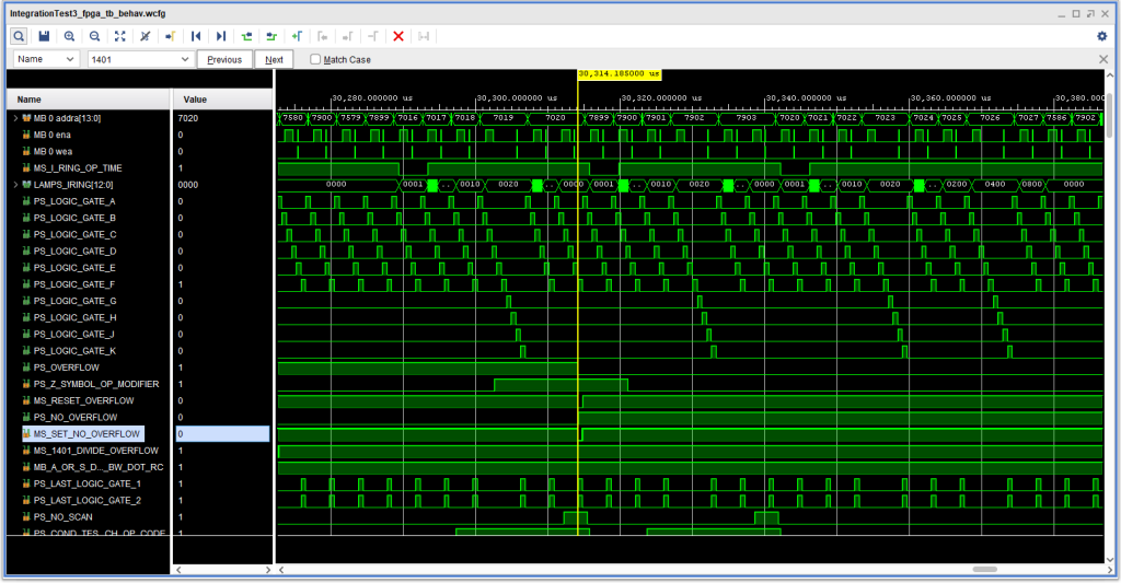
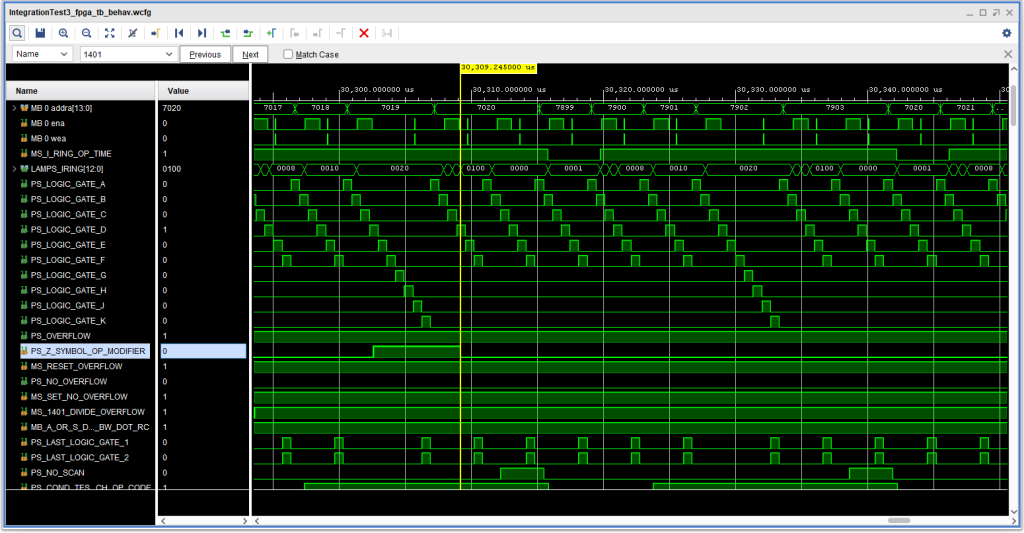
Trouble was, the overflow indicator was indeed off after executing the branch instruction at location 7016 (which branches to location 7899, which was set up to just branch right back to location 7020.) What is so special about the “Z”? Well, it turns out the “Z” is the d-character for a B(I)Z instruction – branch on overflow (a sample of which is at location 7027). But why should that ever be in the Op Modifier register for an unconditional branch instruction that has no “d” character?
Well, it turns out that the 1401 mode instruction readout often places a character from the address into the Op Modifier register, as noted in the IBM 1401-1410 Compatibility CE Instructional Manual, Figure 3B on page 9.
There were a few possibilities for this problem, and a few possible cures for this. In the end, some simulation runs demonstrated that the reset occurred because “Z” was indeed still in the Op Modifier register when the unconditional branch was set up.
There were several possible cures that might have fixed this, focused on the fact that in a normal B(I)d conditional branch the d character is read out later in the I cycle – so maybe one could reset the Op Modifier register after the address was read out and the following character had a word mark – indicating that the branch had not “d” character at all. But in thinking about it I wondered why this very specific test was in the diagnostic – and as the last test, which maybe meant this was an issue that was uncovered in the field (and perhaps only on machines with the Accelerator special feature).
The reset of the Op Modifier register is controlled on ALD 15.38.04.1. Interestingly, a very relevant signal, +S CHAR TEST BRANCH OP CODE that this page says originates on page 13.13.05.1, does not show up on page 15.38.04.1 as a destination. I had had to “add” that signal into the signal list when I came to page 15.38.04.1 when I entered the data for that page into the database. Perhaps more interestingly, the Instructional Logic Diagram for this ALD, part of ILD Figure 26, shows the signal as instead being +S 1401 COND TEST OP CODE , and is designed to reset the Op Modifier register when:
- +S 1401 COND TEST OP CODE is active AND
- In 1401 Mode AND
- The B Channel has a WM Bit (i.e., end of the instruction) AND
- Logic Gate D AND
- I Ring 8 Time
Well gee whiz… this was exactly the kind of signal I was looking for to fix this problem. So, to fix it, all I did was change +S CHAR TEST BRANCH OP CODE on the ALD to the one the ILD specified, +S 1401 COND TEST OP CODE, and the problem was cured, with no side effects causing other problems.
So this was presumably a case of either a) a mismatch between a page denoting it is for the ACC feature (15.38.04.1) and the source page of 13.13.05.1 which does not call out the ACC feature, or, perhaps, page 15.38.04.1 being “down level” – not having a necessary ECO t fix this. When I did the change, I set up an “ECO” JRJ005 in the database.
With this, the 1401 diagnostic M011A runs to completion without errors, as does the 1410 CPU diagnostic CU01.
During this testing, however, I discovered an issue affecting both 1410 and 1401 mode: Console I/O Input does not work – the characters don’t seem to make it into “core”, and when Inquiry Release is pressed, the I/O operation does not complete. This could be something as simple as a support console software bug or, more likely, an issue in the interface between the 1415 console emulation VHDL and the 1411 CPU Channel, since 1415 Console Input during console control operations (setting addresses, memory data, etc. all seem to work mostly OK). Time will tell.