Over the past couple of months I have been working planning, and now, this last week, installing a radio antenna suitable for Ham frequencies (in particular, 10, 20 and 40 meter wavelengths).
The antenna installation comprises:
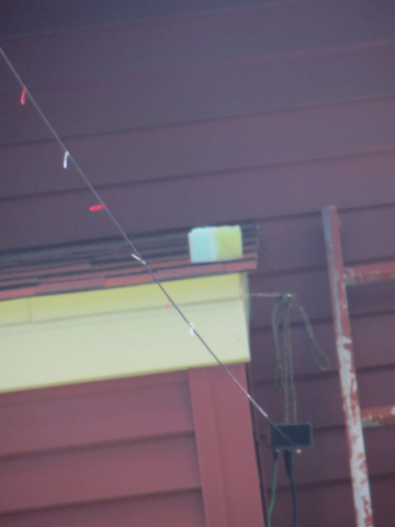
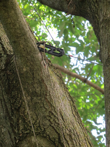
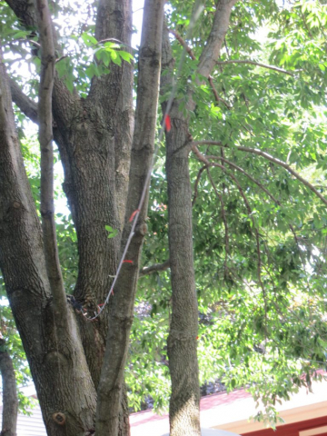
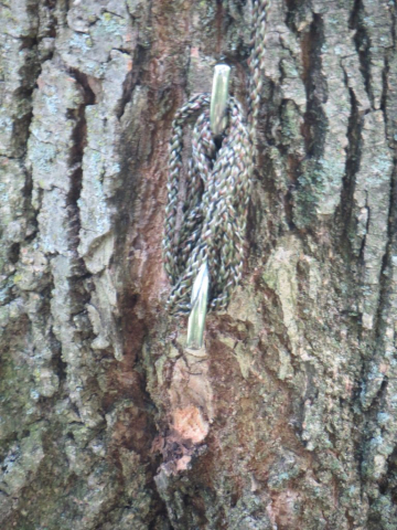
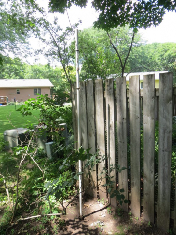
- A 60′ plus antenna wire, run from our cut-off chimney, then passes though a tree supported from a limb, and then is attached via a rope to a 10 foot high PVC pipe which is sunk into the ground 2 feet, which provides support for the far end (and keeps it well above my head.)
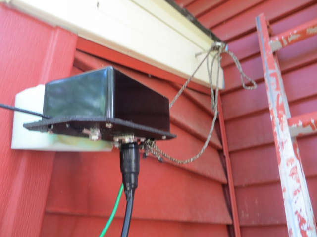
- An antenna matching transformer that matches the relatively high impedance of this “end fed dipole” antenna to the 50 ohm impedance of the coax feed line attached to it.
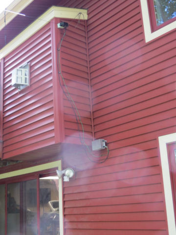
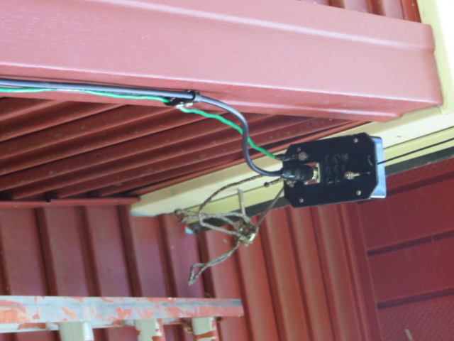
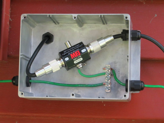
- A safety ground the leads down from the box containing the antenna matching transformer, to a metal box which connects this to the lighting arrestor ground and a ground that runs off to the inter-system ground (see below.)
- A lightning arrestor which is installed into the feed line, and which connects to the feed line into the house.
A big difficulty with my antenna installation was grounding. An antenna must have a ground, both to “work”, but also to provide static discharge to discourage lightning strikes.
If lighting strikes a typical antenna, it will vaporize and likely damage any equipment attached to it – that is not what the safety ground is designed to prevent. Rather, it attempts to discharge pre-lightning voltage build-ups.
An ideal ground is directly below the antenna, with a 6 foot or so rod driven into the soil. However, if that is done, it is also crucially important to “bond” that ground rod with any others on the property (such as one installed by the electric company.) The reason this is so important is that if lighting strikes the utility lines, it wants to find its way to ground, and will happily do that through your house wiring to find your radio ground, if the two ground rods are not bonded. The reverse is also true if lighting strikes the antenna.
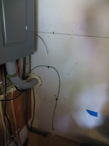
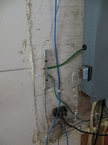
However, in my case that would have meant running the AWG 6 (!!) bonding wire through a rock wall, which was rather impractical. So, instead, I opted to run the safety ground above ground, mounted under the deck, and connect up to the inter-system ground that was installed at my electrical panel in 2017 when that panel was replaced. That connection then connects it to the utility ground rod.
Here are some photos:
Note that the antenna box in the first picture, which contains the matching transformer, attaches to the eye bolt on the chimney with two lines of different lengths. Do you know WHY the lengths are different??? Leave a comment, below.

