
Note: Information on the original design (c) 2013 by Beric Dunn, K6BEZ, is licensed under the Creative Commons Attribution-ShareAlike 3.0 Unported. Information on the original can be found at : http://www.hamstack.com/project_antenna_analyzer.html
Background
After dragging out my Sears-branded Yeasu FRG-7 shortwave receiver, I strung up a “random wire” antenna. I find it does not work that well – largely, I think, due to noise. Adding a Nooelec 9:1 balun (being used as an unun) increased signal levels some due to a better impedance match, but did not help the signal/noise ratio at all.
I do recommend the Nooelec 9:1 balun. I had some questions about it because it indicated it was an unun (unbalanced to unbalanced device), but when I received it, I found it could not be wired as the typical autotransformer style unun. But there is no reason why a balun cannot also function as an unun, as near as I can tell. I found Nooelec’s support exceptional – and indeed they ended up refunding the price for the unit, though I felt that was not necessary for them to do.
- Nooelec 9:1 balun on Amazon.com
- Discussion of using a balun as an unun online at https://forums.qrz.com/index.php?threads/what-exactly-is-an-unun.259423/
I am also working on a so-called “magnetic loop” antenna, so I realized I was going to need to be able to analyze its impedance, and to tune it, so I started researching antenna analyzers online.
At the time I had not yet spotted the “Nano Vector Network Analyzer” units available on Amazon and eBay – they didn’t show up on a search for “Antenna Analyzer”. Had I been aware of this unit, I probably would have just bought one. 😉
Prototype / Breadboard
But I did spot the K6BEZ Antenna Analyzer, and it piqued my interest. I first constructed the unit on a breadboard, using a couple of germanium diodes and an Arduino Uno I had on hand to make sure I had the circuit correct and that it functioned reasonably correctly. The results from this test (as a PDF) are in the link below and gave me enough confidence to proceed with my project.
PDF of testing results for breadboard version of the analyzer.
The basic design uses an AD9850 direct digital synthesis (DDS) module to generate the testing output signal. The AD9850 is controlled from an Arduino Micro microcontroller, and is used to generate sine wave outputs from 1MHz to 30MHz. That is then fed to an antenna, and to an SWR bridge – 3 51 ohm resistors with the antenna and its ground as the fourth leg of the bridge. The original output, as well as any reflected signal coming back from the antenna are then each half-wave rectified and filtered, and fed to a pair of operational amplifiers in a single IC, which are then fed to the Arduino Micro’s analog inputs. The Arduino Micro, in turn, communicates with a PC to control its functions.
IMPORTANT: Not all of the DDS modules based on the AD9850 use the same pinouts. The one I used, available from HiLegto on Amazon, is labelled HC-SR08 on the back side of the DDS PCB.
PCB Design
I then proceeded to reproduce the schematic in KiCAD, and lay out a PCB based on an Arduino Micro and the aforementioned direct digital synthesis module. The result was this PCB:
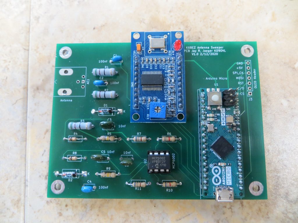
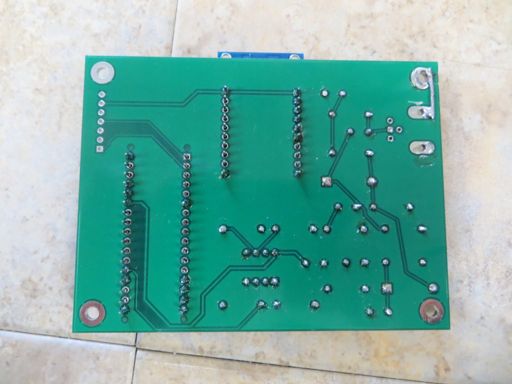
Note the soldered wire on the bottom view? Unfortunately, the PCB footprint intended for a BNC connector mounted on the PCB board that I chose was not a wise choice, and I forgot to ensure it was connected to ground. The wire is to correct that oversight. Also, it wasn’t the best choice of footprints – it does not match ANY of the PCB mount BNC connectors that I saw on Amazon – something I really should have checked beforehand. It also does not provide as large a hole for the center conductor for a coax as one might desire – though it should be enough.
As one might expect, with the shorter connections among the components afforded by the PCB, the test results improved somewhat.
Test Results for the PCB version of the antenna analyzer
As one can see from the comments in this second set of test results, the software could use some improvement. (I have seen hints to “newer” software on some pages, but the links are always broken.) In particular, it sometimes gives negative SWRs – I think maybe it should be taking the absolute value of the difference in voltage to handle cases where the reflection comes back as a positive voltage, therefore resulting in a higher voltage on the input as compared to the original.
Would I do this again, knowing about the Nano VNA? Probably not. Still, it was fun. Besides, with just a bit of work on the software, this little PCB can do more than just analyze antennas.
Possible Enhancements
Without a whole lot of work to modify the microcontroller and PC software, this device could also be used as a simple signal generator and as a sweep generator (e.g., one that could be used to align a 455 KHz IF on an older receiver)
Resources
- Information on the original design (c) 2013 by Beric Dunn, K6BEZ, licensed under the Creative Commons Attribution-ShareAlike 3.0 Unported. Information on the original, can be found at : http://www.hamstack.com/project_antenna_analyzer.html , and includes the following:
- Original Schematic
- Arduino Microcontroller software
- PC Software
- Source for the PC Software
- Documentation, including a slide show as a PDF file
- The schematic for this board as a PDF file
- The schematic and PCB information for this board- KiCAD files (zipped)
- The HiLetgo AD9850 DDS module can be purchased from amazon here.
- Further information on the HC-SR08 AD9850 DDS module can be found here.
- PDF of testing results for breadboard version of the analyzer
- PDF of testing Results for the PCB version of the antenna analyzer
- The Nooelec 9:1 Balun that I used for an unun can be found at https://smile.amazon.com/gp/product/B07XJRTF94/
- A good discussion of using a balun as an unun can be found at https://forums.qrz.com/index.php?threads/what-exactly-is-an-unun.259423/