
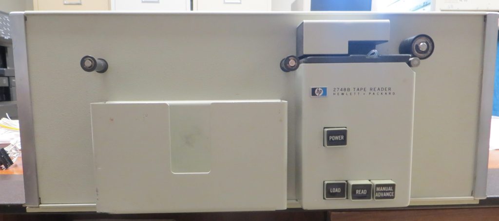
An denizen of the Classic Computer mailing list approached me recently about getting some paper tapes read in. These were BASIC programs from his High School days. At first I tried reading them in my PC05 paper tape read on my PDP-11/34, however that reader has a sprocket feed, and no good place to hold a rolled up tape. I tried 3D printing a spool reel holder and output guide, that that was not successful. So I decided I would try instead to use one of my two HP 2748 paper tape readers – an HP 2748B in particular.
Note that this reader has a capstan (small cylinder to the right) and a pinch roller (the larger black roller to the right) to firmly grip the tape and pull it through the read station. It works pretty well, but I do have to clean it frequently when reading oiled rolled tapes or they start to slip. Fortunately, both the capstan and the pinch roller are metal – no chance for rubber rot turning to “goo” here!
The Arduino “Sketch” described in this post, the PC side perl script, and some perl script tools for working with paper tapes for 8080 machines, PDP-11 and PDP-8 are available for download.
The jig I used to install new grain-of-wheat lamps into the read head is available on Thingiverse .
Documentation is available for this reader at https://bitsavers.org/pdf/hp/paperTape/
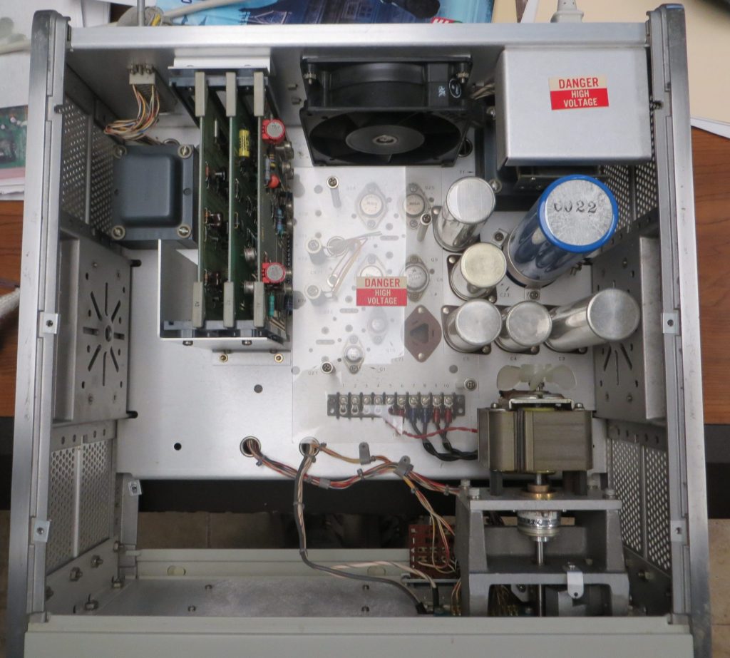
A gorgeous device inside
Like many/most HP devices, this device is absolutely gorgeous inside. Gold plated printed circuit boards (the entire board, not just the contact fingers), lots of space to work inside, easy disassembly and reassembly.
A Continental Connector for the Interface
The first challenge was the connector. It is a 50 pin connector originally made by Continental. First I bought a Winchester connector off of eBay, but its pins were much too narrow. Then I purchased an AMP connector of eBay, and its pins were just a little bit too narrow. For now, I added solder to the relevant pins to ensure they make contact. Some are still a bit too wide and need some filing down so the connector mates fully, but it works well enough, for now. I will not be leaving this connector attached permanently because of the solder. But I thought it was a better than the alternative of wiring up a second interface connector.
The default logic voltages for the interface are +/- 12V. However, HP also planned for a TTL logic level interface (0 – 5V) by adding a clamping circuit on each interface connection. This clamping is activated by connecting interface pins C and H. Unfortunately, my AMP connector had a coax connector on pin C, so for now I made this connection internal to the reader. When I get some time, I’ll se if I can swap pins so I can make this connection in the way the designers intended.
My plan was to use an Arduino to drive the paper tape reader, and connect to that via TCP/IP, similar to how I did my paper tape simulator.
It’s ALWAYS a Light Bulb
The first thing I did was re-form the capacitors. This turned out to not be necessary. For one thing, most of the power supply capacitors are rated at 5 TIMES to 10 TIMES the expected voltage across them. There was almost no current flow after a minute or two of “reforming”.
The next thing I thought of (thankfully) was to check to see if the illumination in the read head was OK. Well, of course it wasn’t (though the lamps in my other HP paper tape reader, an HP 2748A, turned out to be OK).
Unlike the DEC paper tape readers, these HP readers use a grain-of-wheat lamp for each channel: 10 lamps in all, 8 for the data channels, one for the feed hole, and one additional lamp used for temperature compensation. Clearly at least one was bad, but it turned out to be much more confusing than that.
I had some lamps on hand that are ostensibly for an RK05 positions sensor, but when I tried to replace the lamp I thought was bad (and at that point, I thought it was just one), another one seemed to fail. I took out the lamp I thought was bad, and tested it – and it seemed OK. Put it back in, and it seemed bad. Eventually I figured out that what was probably going on was that the wires on the lamps were so corroded that solder wasn’t taking properly to the leads. Eventually I decided to order some likely replacements off of eBay and replace all of them.
The process of lamp replacement is sufficiently tricky and time consuming that HP service people generally were not expected to do it in the field. The bulbs aren’t listed as replaceable components. Instead, service people / customers were expected to acquire a replacement for the entire read head.
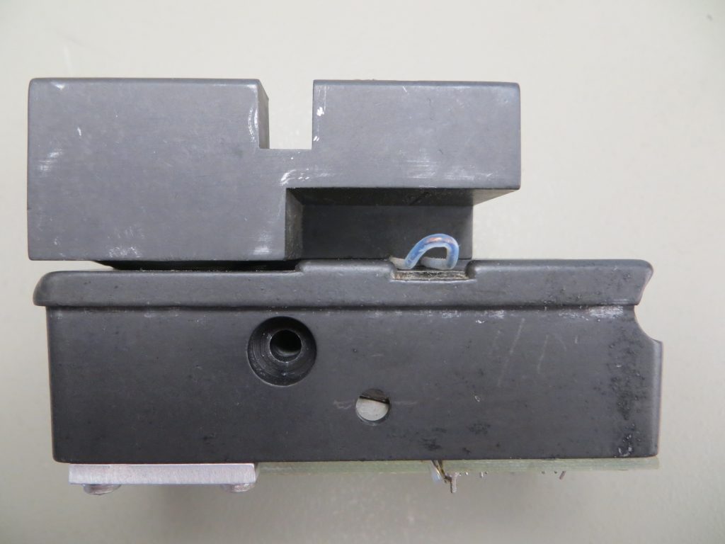
Metal alignment pins at least make the removal and re-installation process relatively straight forward – takes about a minute.
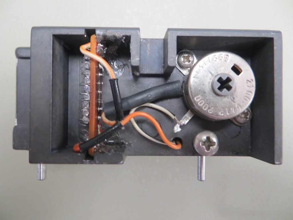
To do the replacement, I removed the little PCB (left side of the photo), unsoldered everything, including the wiring to the rest of the read head, and install new lamps. I had already learned from experience that getting a single lamp into position could be tricky, so I didn’t relish trying to do what with eight of the little wee beasties. In order to assist the installation, I made a 3D printed jig that fit the boards and had a place for each bulb at an appropriate distance from the PCB based on the lead lengths of the original lamps that I had removed.
I made this jig available on Thingiverse .
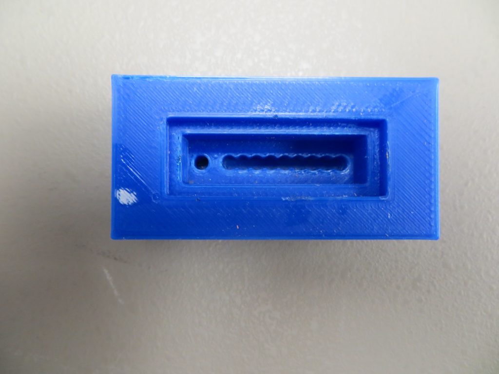
It still wasn’t easy – at 70 years of age I am pretty shaky at times (and have been more shaky than average my entire life), but it worked well enough. However, since these bulbs are slightly different than the originals, I ended up adding a fixed 1/2 Watt resistor to add some additional resistance. That resistor is inside the black heat shrink tubing that goes from the adjustable resistor in the top view over to the PCB.
Then I used silicone sealant to hold the board in place, much as had been used originally – messy, but effective.
Adjustments, Adjustments
Next, I adapted the “solder enhanced” AMP connector to the tape readers interface connector. That took some trial and error in terms of how much solder to add so that I had good reliable contact. It still isn’t perfect: some are a bit too large right now.
Then I was ready to adjust the read head. Fortunately, there are good instructions in the manual (see the link at the top of this post) for how to do that. I ended up going thru that process several times, but in the end it ended up about where it was after the first time.
During this process I was also able to verify the interface signals were behaving as expected. It took a minute or ten to figure out that the read hole signal would not be present unless the READ button on the reader was engaged. Also, at first, I misunderstood the lamp/bit order – on this reader the feed holes go nearest to the front panel when inserting from left to right – the opposite of a DEC PC-05 reader.
The Arduino Interface
For this application, an Arduino Uno had sufficient interface pins, and unlike the Raspberry Pi, is supports 5V interfacing. The code was relatively straight forward, and uses the same kind of program I used for the paper tape emulator I called out earlier – the PC just makes a TCP connection and sucks up data.
The interface pins for the HP Connector, the Arduino and the Arduino digital signals are all documented at the top of the code, and symbolic constants and macros are in place for handling the Arduino port setup and usage.
There were some things I learned/ tweaked along the way:
- At first I tried to stop the reader every time I sent a buffer of data to the PC. However, the clutch and brake on the reader don’t seem to be working quite well enough for that to succeed, so in the end I just streamed the data an “hoped” the Arduino and the TCP connection would keep up – and it seems that they do.
- Originally I though I might have some kind of header on each buffer of data I sent, but it occurred to me that TCP is essentially doing that already. The code for that header is in SendBuffer(), but is commented out.
- I was having problems with some extra characters, so I added a little time wasting loop to more or less ignore rapid transitions on the h0le signal. That code could probably be improved upon.
It is Working – Trust but VERIFY
After a couple of passes of tweaking the lamp positions and going through the adjustments, the reader reads a DEC test tape pretty reliably – maybe 1 error every 50,000 characters. It also handles both fan folded and wound “round” tape spools well. However, I always try and verify that tapes read correctly, so I wrote some perl scripts to do things like:
- Verify 8080 binary tapes (the format is documented in the script)
- Verify 8 Bit Intel HEX tapes
- Verify Even parity text tapes
- Verify PDP-8 binary format tapes
You can download a Zip archive with these tools, the Arduino Sketch and the PC side Perl script here.
One More Problem – There’s Always at Least One
As I started reading in tapes, starting with the DEC test tapes (MAINDEC-00-D2G2-PT and MAINDEC-00-D2G4-PT) things were fine. As I proceeded to read in some 8080 binary tapes, I started having some issues with the high order bit. That was easy to fix – the lamp was slightly miss-aligned.
I also found finding the balance between not having data errors (dropped bits) and having duplicated characters a little tricky – it took me a few passes doing the adjustment procedure described in the HP manual to get it working well.
However, I then discovered one more problem. Sometimes it would drop some of the null characters appearing in a blank area of tape after the initial leader. The HP 2748B has a special circuit that causes it to intentionally drop leader nulls – once you hit the READ button, it drops nulls until the first character. After trying this and that (including running through the adjustment procedure yet again), it occurred to me that maybe that circuit was firing, causing the reader to drop nulls.
I connected several signal lines to a connector that I thought might be useful in order to scope them (and not have to keep moving the scope probe around the board, as I have no extenders for these connectors), and quickly confirmed my suspicion. I tried a lot of things – including swapping some of the four identical transistors (two for a flip flop, and two more acting as signal inverters) so that the flip flop would have matched transistors, to no avail. I also tried replacing the capacitor that connects to +12V that resets the flip flop on power up (in case the READ button is already pressed). Nothing seemed to help.
I noticed on the oscilloscope that the length of time before the circuit fired when it shouldn’t was kind of random. Could this be noise? Connecting a .1uf bypass capacitor on the +12V line feeding the reset circuit was the first thought, but that was going to be harder to do on the board than I preferred. In the end, I hooked up the capacitor from the base of the reset signal inverter Q13, and that cured the problem.
Now the reader is generally reliable so long as I keep the read head, capstan and pinch roller clean.