
Having spent the past few months cleaning up my IBM 1410 SMS database program, and posting it to github at https://github.com/cube1us/IBM1410SMS , I have spent the past couple of weeks focused on the HDL (currently VHDL) generation, using GHDL and Xilinx’s Vivado toolset, with an eventual destination of my Digilent Nexys4 FPGA (Field Programmable Gate Array) board.
After fixing a few bugs, and implementing the oscillator (by way of a counter/divider from the 100 MHz FPGA clock), I loaded the results into the FPGA, and as show below, my IBM 1410 now has a clock, running at the right frequency for an IBM 1410 with the accerated throughput feature, as shown below:
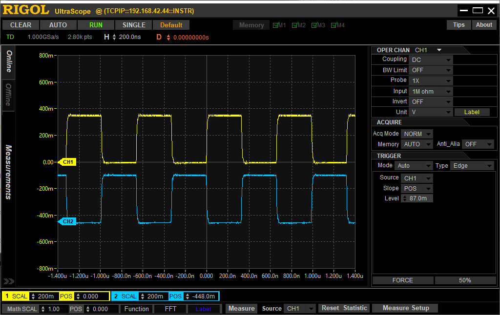
On the original machine the lower signal, on channel 2 of the oscilloscope, was derived from the first using a delay line – about 330 ns of delay. Kinda hard to do with an FPGA. 😉 So, I implemented delay lines using a series of flip flops clocked by the 100 MHz FPGA clock – so, in this case, there are 33 of them.
This signal is not simulated – it is a real signal that exists in the FPGA.