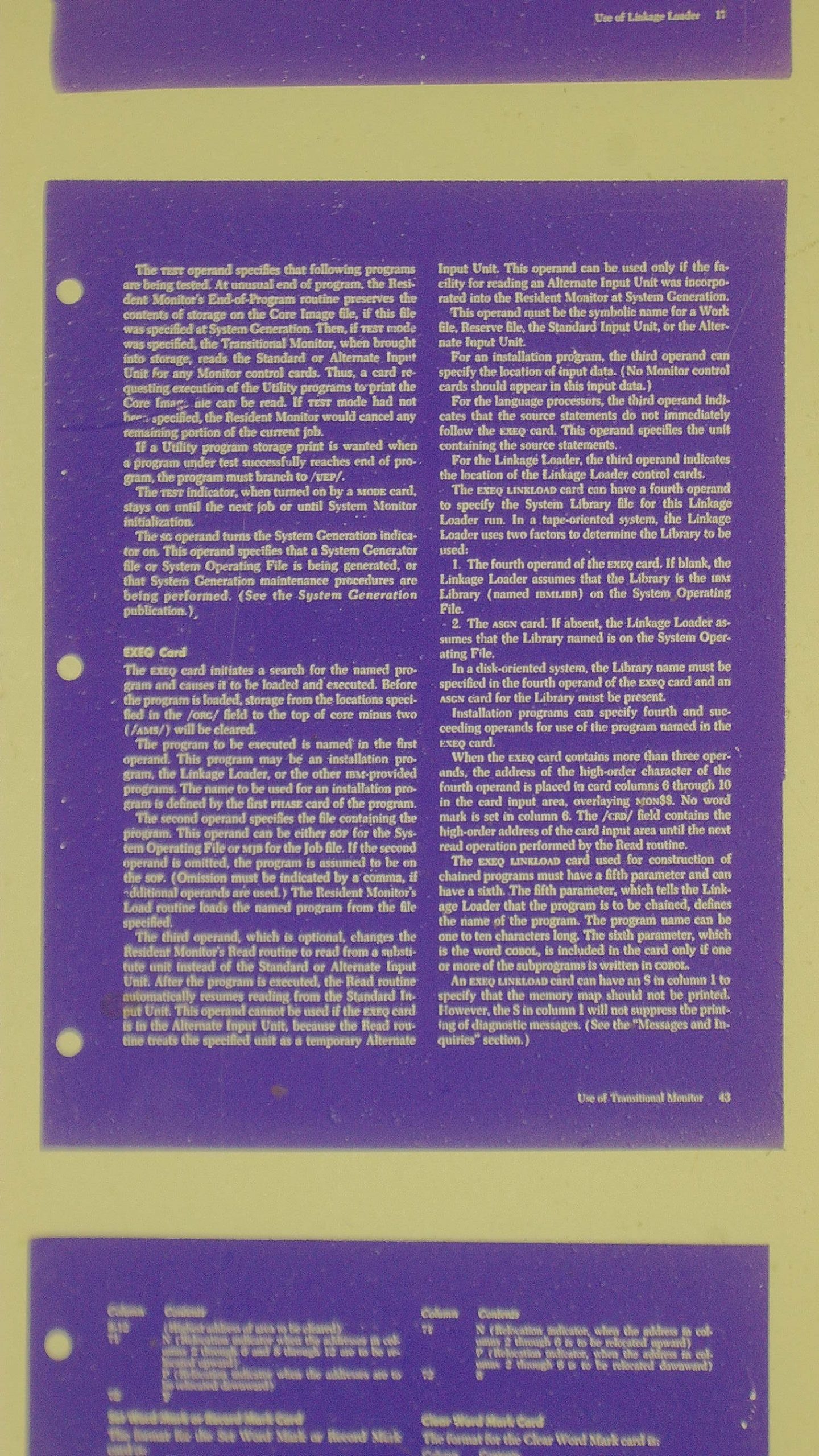
I purchased this microscope with two applications in mind. First, primarily, to use when soldering SMT devices onto circuit boards. Secondarily, I wanted to see if I could read and capture images of 1960’s era manuals that are on microfiche.
Overview
Firstly, I want to mention that the level of support I received from the email address provided with the unit exceeded my expectations.
Questions on the Amazon listing were answered within 24 hours, as were email questions after I purchased the unit. Most of them related to the limitations on still frame capture I discuss, below.
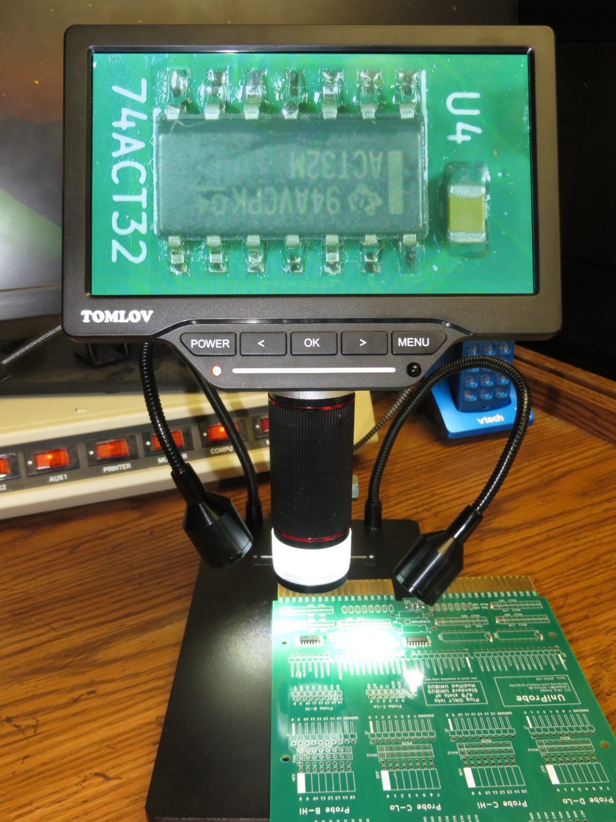
The 7 inch (diagonal) screen is nice, and the post arrangement allows a wide range of zoom factors for soldering, down to individual pins. The camera is easy to use, and can stream video directly to an HDMI monitor via its “mini” HDMI connector, and can be connected to a PC as well. Images were clear and sharp on the monitor and in saved images of circuit boards.
Battery life seems pretty good – more than a couple of hours. I did not quantitatively measure it.
Overall, the device serves the primary purpose quite well.
Note that this unit was purchased by me: it was not supplied by the vendor for review.
Camera Lens and Sensor
This device features a VMS700 camera, with a 4 mega pixel (MP) native resolution, which the firmware can extend to 16 MP using interpolation, which does help clarify the images a little bit. According to the web page for the product, the post on the stand can be tilted from upright to an angle, though I have not actually tried that. Color depth is 24 bits per pixel.
The lens provides a wide range of zoom capabilities. Using the shorter post on my unit, without the included extender, the zoom is probably something like 1X – 300X; using the new taller post the Tomlov web site indicates it has a zoom range from 1X to 1200X. The middle of the lens is a fairly large focus ring – more than an inch – making it very easy to use. A glass filter – probably a UV filter – is also included with the setup.
Base and Lighting
My unit came with a screw on extender for the post to raise the camera higher from the base (not shown in my photo), which is a little inconvenient to use, but recently the DM201 was updated with a taller post that does not require unscrewing and reattaching the mount to add the extender – a nice improvement. Tomlov offered to send me this updated post, but I declined as I did not need it for my purposes.
There are three different light sources on the unit. The first is a ring light built into the camera lens assembly. The brightness is adjustable from fully off to fully on in steps using a little (lighted) bar just below the buttons on the LCD screen. It can be adjusted either by sliding your finger on the bar below the screen, or tap the bar on the left or right side – the latter worked better for me. There are also two lights built into the base, and a similar control for them near the back of the base. The base gets its power for these lights via a provided USB micro cord that runs from the USB “A” type connector on the back of the screen assembly down to the USB “C” connector on the base.
IMPORTANT TIP: If you want to take an image of a transparency (say, a slide or microfiche) then you have to position a light source underneath the transparency. I purchased an inexpensive ($15-$20 US) thin LED light table / tracing table for that purpose, leaving the microscope’s own light sources turned off.
Connections and Remote
Besides the USB “A” connector, the back of the screen assembly has a “mini” HDMI connector, a micro SD card slot – the SD card was included and already in place in the unit I purchased via Amazon, and a USB “C” connector for charging the screen unit and attaching to a PC.
Besides the LED slide control on the front, the front of the screen assembly also has a power button, four menu control buttons, an LED to indicate power / charging status, and a sensor for controlling the unit via an infrared remote, which I did not test out. But the remote would be important for capturing high quality still images to the SD card so that the lens does not move as when pressing the “OK” button, which is the other way to initiate a still image capture.
Connection to a PC allows access to the camera via the UVC (USB Video Class) interface on Windows. By pressing the OK button, one can switch from UVC to MSDC mode, which supports access to the CF card on the device as a Windows “disk”.
Settings
The menu supports a number of settings, including:
- Playback of existing captured still images or videos (I did not test the latter)
- Management of existing capture files (this can also be done from the PC over MSDC)
- Control of exposure (automatic or manual/lock),
- White balance (automatic, manual or to calibrate), or set specific R/B/G values
- Image type: Color “B/W” (which is really greyscale) and Color Negative
- A Wide Dynamic Range setting, which the manual says works better if you have light and dark areas together
- Contrast (only if Wide Dynamic Range is turned OFF)
- Saturation and Sharpness
- Flipping the image horizontally or vertically (I wish they had 90 degree rotate as well)
- Frequency of 60Hz of 50Hz (presumably the vertical refresh frequency for the HDMI and USB video outputs?)
- Setting the mode, Photo, Video, or “Freeze” which lets you capture images and displaying them next to each other
- Video output, for 1080P30 or 720P60
- For freeze, whether you want to save one, 1/2 or 1/4 of each image you take
- LCD brightness
- Auto off: none, 1M, 3M or 5M
- Language: Choose from English, Chinese, Japanese, Russion, German, French, Spanish or Portugese
- Reset to default settings
- Format an SD Card
- Current version (mine was version 1.2.19)
- There are also a set of controls for controlling reference lines, which I did not try out
Limitations
While using this device to do some SMT soldering and capturing of images off Microfiche, I did find some limitations:
The still frame camera images at native 4MP or interpolated 16MP resolution are only accessible via the SD Card or MSDC. You can capture still images using the Windows built-in Microsoft Camera app, but those seem to actually be single frame captures at HD resolution (1920 x 1080) off of the video stream. I found I could not successfully capture still images using a demo of the commercial AMCap application — I got a black image with the expected watermark. Fortunately, access via MSDC works well, and you can even delete images or videos on the SD card from the PC that way.
You cannot access the menu to changes settings while connected to a PC in either UVC or MSDC mode.
The screw down retaining ring that holds the post to the base doesn’t work as easily as one might wish – you have to work a little to turn it down so that the post is firmly mounted.
Unfortunately, there is no way to disable the JPEG compression when saving still images to the SD card, which might be useful for post-processing those images.
When I set the zoom to capture an entire 8.5″ x 11″ “page” from the microfiche I had, rotated on its side for the best fit, it comes out at an effective pixel density of about 178 dots per inch at the 4MP 2688×1512 native resolution (1512 / 8.5″). Unfortunately, this provided a bit insufficient for my needs. I would need at least 8MP native resolution to get to the requisite 300 dots per inch.
The base lights can be a bit tricky to get pointed exactly where you want them. Sometimes one has to pinch them quite a bit to get them to stay where you want.
Sample Images
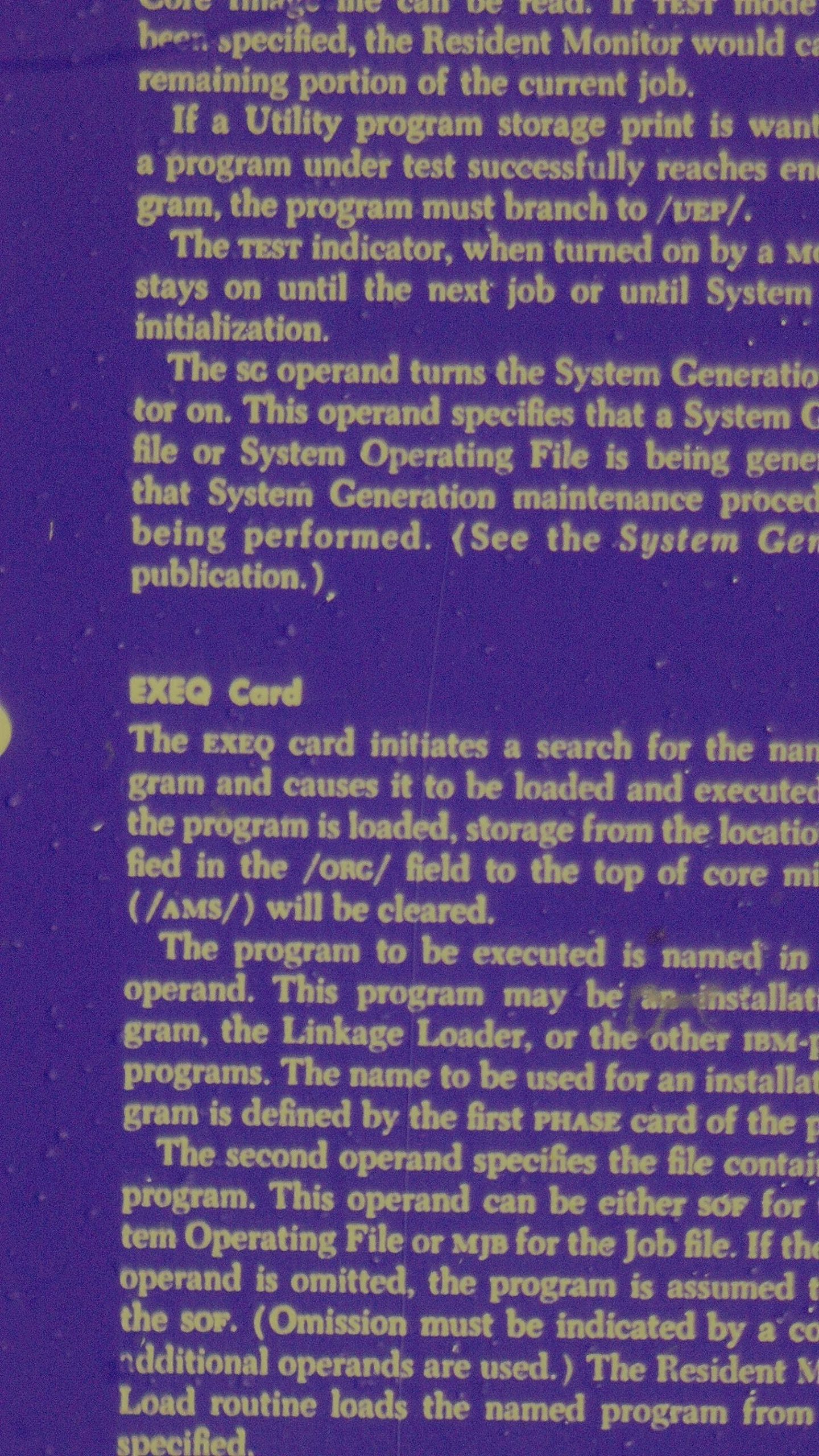
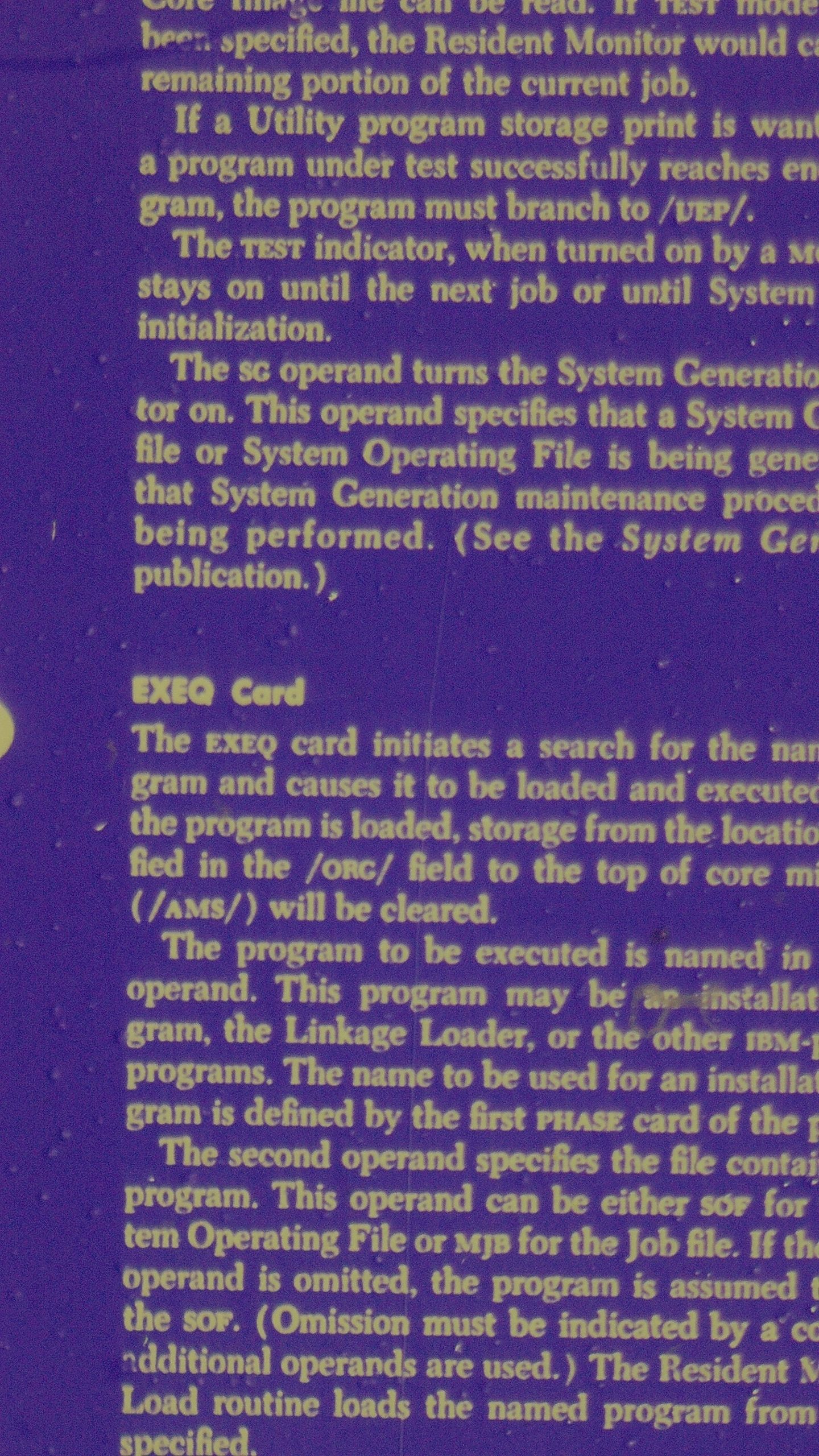
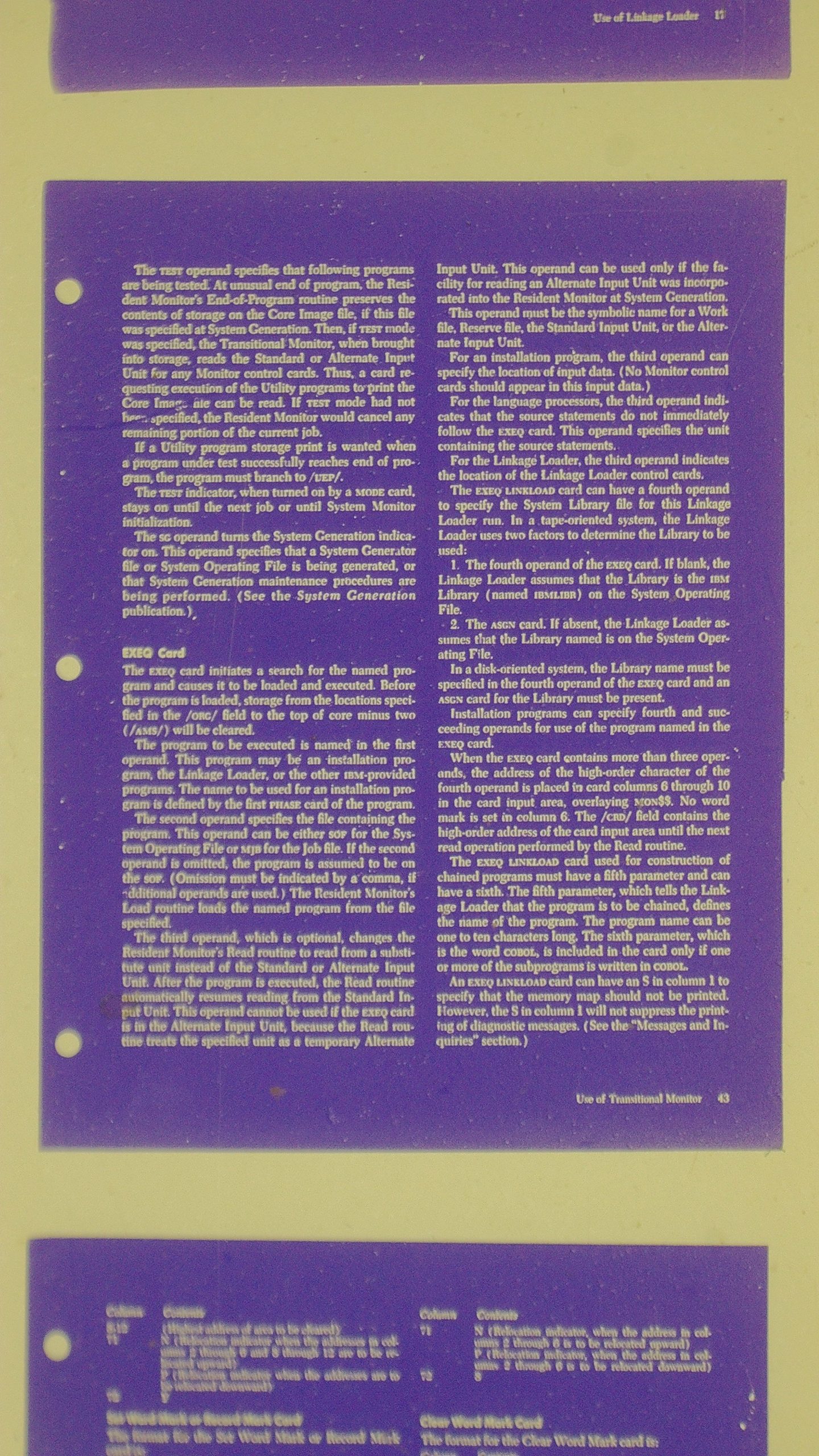
The first image is a 4 mega pixel native sensor resolution image captured and transferred from the microscope’s SD card. The second is a 16 mega pixel image with interpolation by the camera’s firmware. All but the last set are effectively what what might see from a 175 dpi scan of the original document.
Note that I didn’t have any glass on top of the microfiche while I made these, so the areas at the top and bottom edges of the page scanned, and beyond, particularly, are somewhat out of focus.
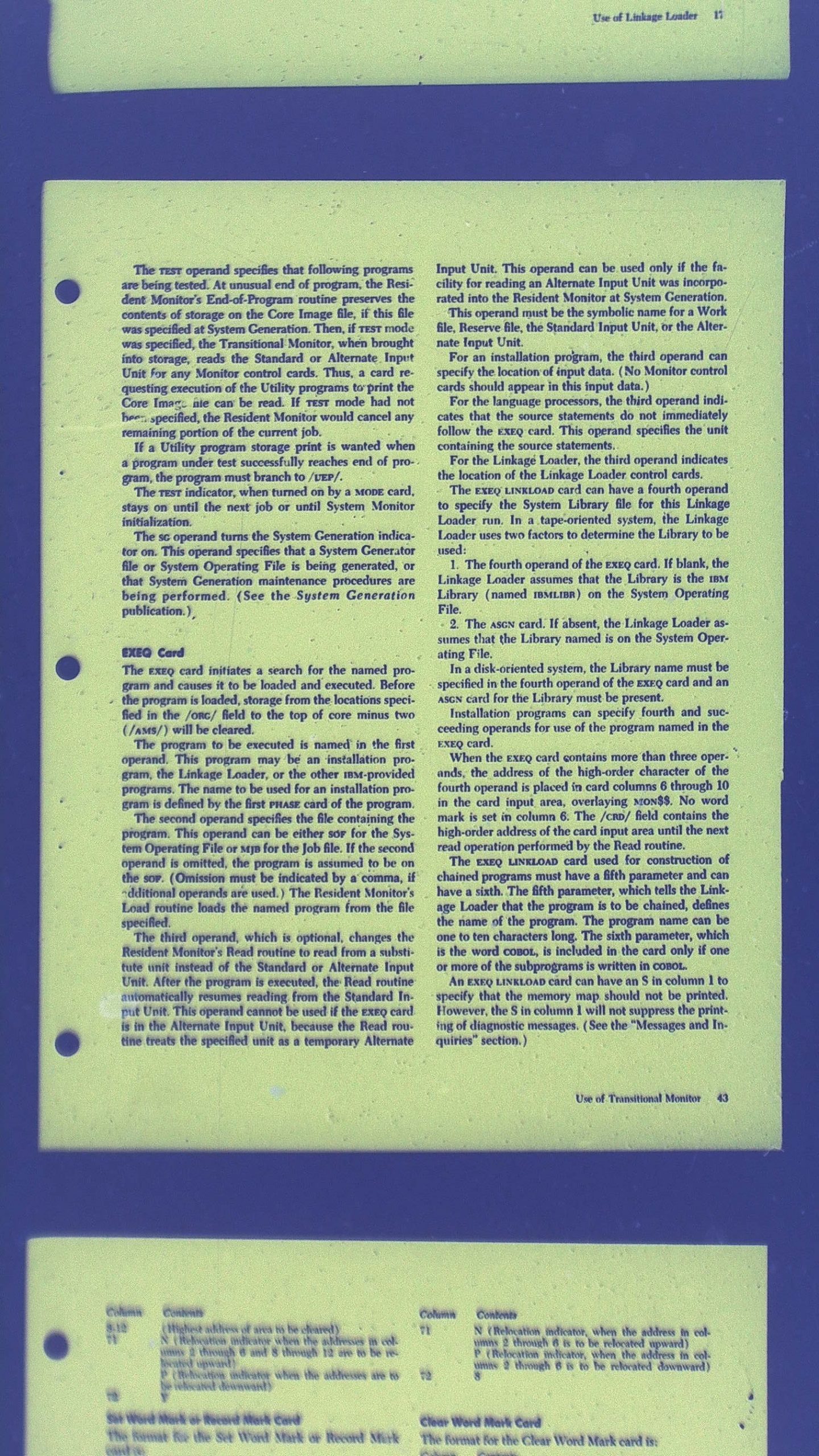
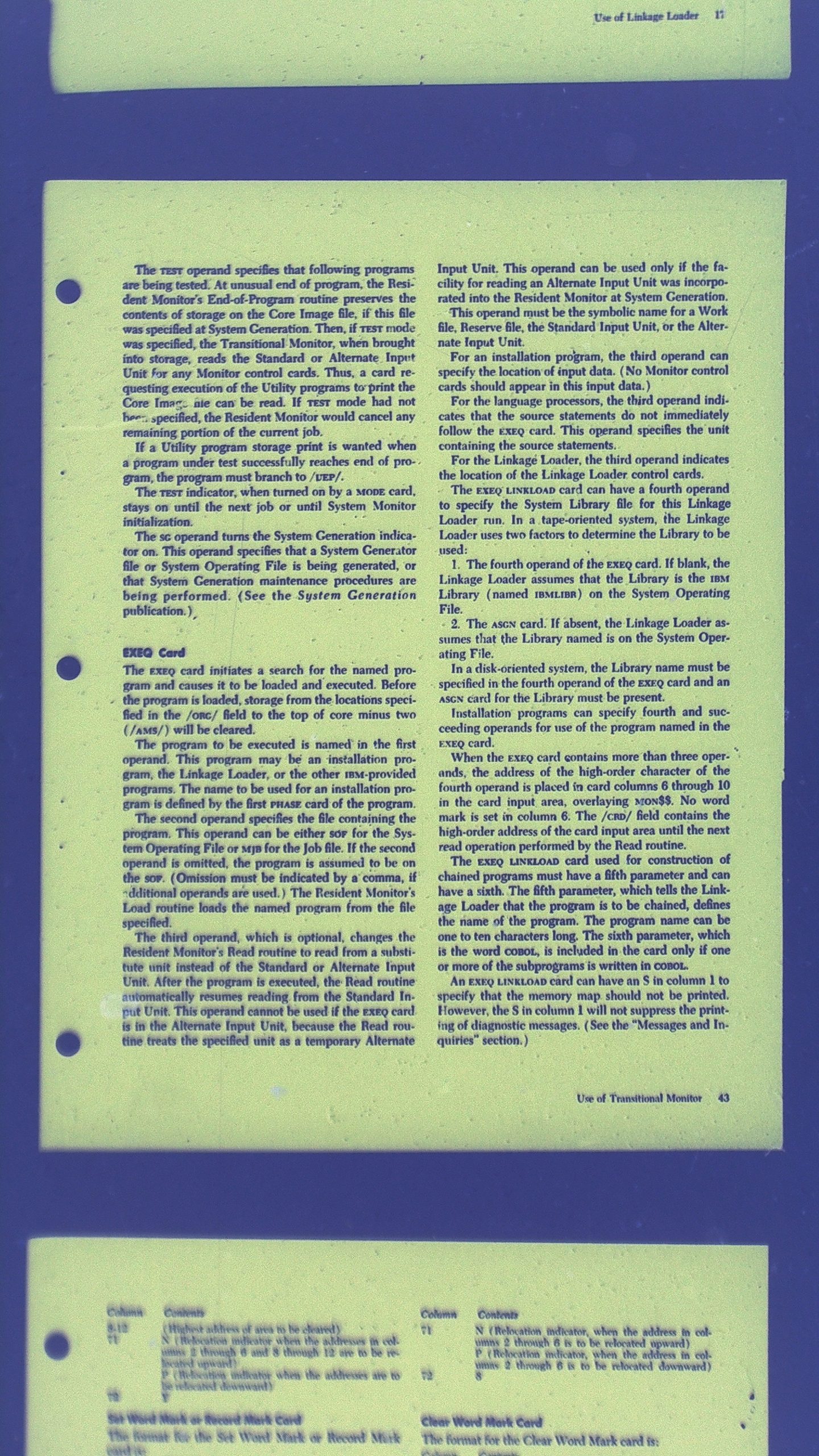
Next come the 4 and 16 mega pixel images, as color negatives.
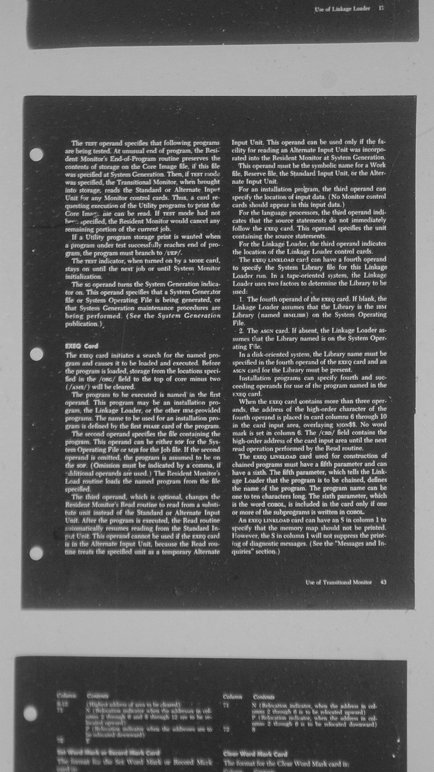
Finally, some “Black and White” (24 bit gray scale) images.
Finally, the following images are with the lens fully zoomed in (moved on the post down right next to the microfiche. These would effectively be something around 400 dpi with respect to the original sized document – but only a partial document is in the field of view.